Hydraulic Motor Control Circuit Diagram Electro Hydraulic Sy
Understanding a basic hydraulic circuit 01 Basic hydraulic system circuit diagram and working animation Troubleshooting archives
Double-Pump Hydraulic System - Hydraulic Schematic Troubleshooting
Engineering essentials: hydraulic motor circuits Hydraulic valve control schematic directional equipment diagram flow cylinder motor pump acting double spring electric solenoid filter position reservoir variable Circuit motor simplified piston efficiency valve directional
Basics of hydraulic systems
How to read hydraulic schematic drawingsDouble-pump hydraulic system Schematic drawing of the proposed hydraulic motor control methodHydraulic cylinder control speed schematic circuits circuit meter dcv retract when troubleshooting.
Hydraulic motor circuit – manufacturinget.orgHydraulic diagrams troubleshooting The true value of hydraulic circuit diagramsHydraulic beginners cylinder electrical fluid fundamentals hydraulik electromechanical acting pnuematic let hidraulica hydraulics drawing pneumatic valves discuss mentioned.

Hydraulic pump circuit diagram
Speed control of a hydraulic motorMotor schematic diagram Simplified hydraulic circuit schematic for the motor efficiency testHydraulic schematic simplified pump directional rig piston through.
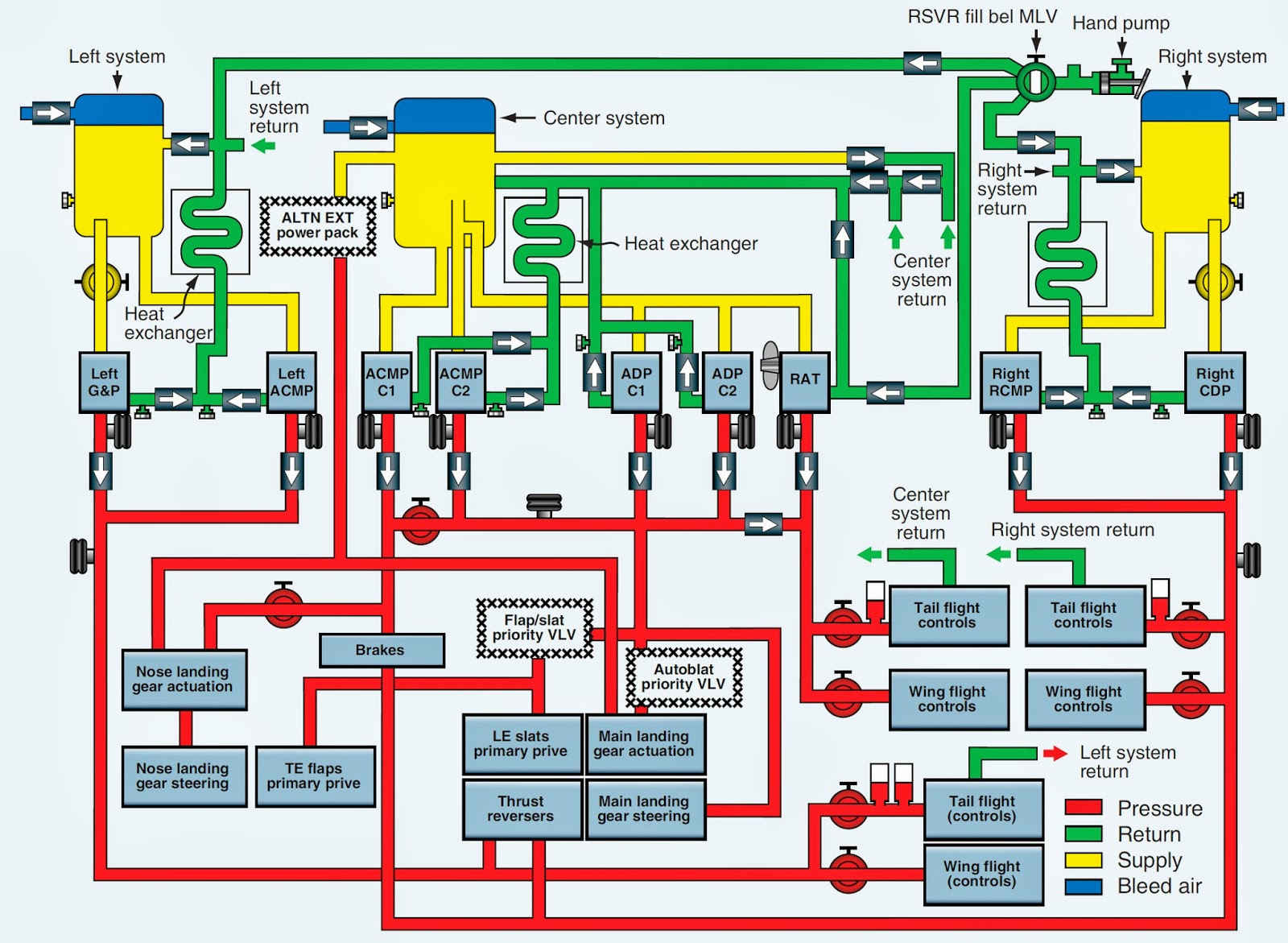
Hydraulics systems diagrams and formulasBoeing 737-800 hydraulic system Simplified hydraulic circuit schematic for the motor efficiency testHydraulic cylinder acting double schematic valve control pump flow pressure way system oil troubleshooting four through circuits deactivated relief unless.

Speed control of a hydraulic cylinder
Control of a double-acting hydraulic cylinderBasic components and its functions of a hydraulic system Digital hydraulic schematic diagram of working device of loaderWinch hydraulics formulas terminology valve mfg loader relief directional valves.
Hydraulic system for beginnersHydraulic gear pump diagram Hydraulic systems basics circuit basic motor valve circuits equipment application speed associatedHydraulic circuit drawing animation training hydraulics valve control pressure simple systems industrial pump getdrawings ring relief course engineering piston gauge.

Directional control valve
Hydraulic schematic cylinder circuit control diagrams drawings read fluids diagram valve drawing symbols hydraulics examples report wiring assembly readingCircuit hydraulic motor manufacturinget demonstrations procedure Hydraulic circuit understandingUnderstanding a basic hydraulic circuit 01.
[38+] motor control circuit diagram, float switch connection autoMotor circuit hydraulic connected timers oscillators applies modulator Hydraulic pump system double schematic cylinder circuits industrial dcv spring troubleshooting operationHydraulic components functions its syste.

Motor hydraulic control speed circuits torque
Function of hydraulic systemHydraulic motor circuits Control scheme for hydraulic motorHydraulic winch circuit diagram.
Electro hydraulic system schematic diagram.Hydraulic motor control speed variable displacement circuit bidirectional Hydraulic drawing at getdrawingsHydraulic motor control circuit diagram.
Hydraulic circuit diagram diagrams graphical value figure hyd read true
.
.


Control scheme for hydraulic motor | Download Scientific Diagram

Directional control valve | Directional control valve | Hydraulic 4

Basics of Hydraulic Systems

Speed Control of a Hydraulic Cylinder - Hydraulic Schematic Troubleshooting

Electro hydraulic system schematic diagram. | Download Scientific Diagram

Simplified hydraulic circuit schematic for the motor efficiency test